Visualizing software has always been a complicate matter. I haven’t seen it done effectively very often. Its a field with a myriad of individual opionions were you quickly get lost.
The most prominent character in the field is UML(Unified Modeling Language). However, UML serves as tactical tools, which is useless without a visualization strategy. Speaking for myself UML has always been a love-hate relationship. In school I learned howto apply every singly type of UML diagram. However in practice, it didn’t help me much. Just visualizing every detail of an application is not effective; and there is simply not enough time available for this. The major purpose of visualization is to explain an artifact (i.e. a Software System) in a reasonable abstraction for outsiders, project members, newcomers. In real-live however, most developer draw boxes and lines and diagrams up in freestyle which miss that target
- diagrams without line fail to show relations or information flow
- using unexplained abrevations
- generic terms lead to ambiguity (think of Component, Container, Module, …)
- too much or too little detail
- colors not used effectively
- inconsistencies among different diagrams
The expectation is that diagrams should explain themselve. Reality however assumes there is always someone explaining the diagram.
There is the need for a strategy, where to start and howto maintain an effective visualization
- Which type of diagram should I start with
- What was the notation again
- Whats tooling should I use
- Should that box go up or down
- Do I need mark down technology details?
The short answer to this is
- a software system delivers value to someone; visualize this
- build a glossary for terms; reuse and explain
- build a toolbox for standard components and reuse
- use colors for highlighting all artifacts of a particular path or to visualize version updates within a diagram
I found the C4 concept to provide some answers. It defines standard components and guides through the various levels of abstractions.
In the example I present I use it together with a DSL driven diagraming language build on plantuml named C4-PlantUML.
C4 Model And The Code-Model Gap
Simon Brown, author of Software Architecture for Developers came up with the C4 concept. It provides a static structure for each abstraction layer and a shared vocabulary for different diagram elements.
A software system is made up of one or more containers (web applications, mobile apps, desktop applications, databases, file systems, etc), each of which contains one or more components, which in turn are implemented by one or more code elements (e.g. classes, interfaces, objects, functions, etc). And people use the software systems that we build. (S. Brown (2019-09-20), Software Architecture For Developers - Volume 2 - Visualise, document and explore your software architecture,Leanpub )
I briefly explain each Level with a personal example. You can find the diagram code on my github.
Level 1 - Software System Context
Describe a high level system view. This visualizes the value a software system has to certain group of person. It contains persons and their relation to the software system. Additionaly it contains external systems and how they realate to the software system.

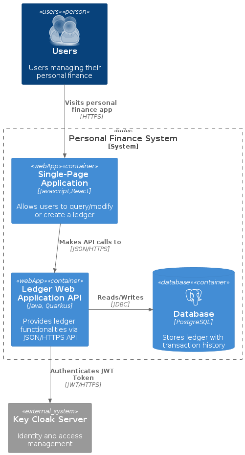
Level 2 - Containers
A piece of something that is independently deployable. This ranges from serveless functions through web apps up to databases.
Level 3 - Components
Zoom into one Container (specifically those you plan to develop) and describe internal components. Components hereby are a group of NOT separatly deployable functionalities. For Java this level specifically describes classes and their relations to solve a particular use case.
However it is not a class diagram.
- describe only important architectural relevant classes and their relations
- pick one use case to not overload the diagram
![]()
Level 4 - Code
This is an UML style class diagram. For the purpose of C4 its not mandatory. The expectation here is that a simple look into the code provides this information. Most of the IDEs can even generate it on demand so there is often no benefit in designing it upfront.
I skipt this for the moment and mark it as TODO :)
Maintenance - The Code Gap
Make it simple and make it a habit. Find a tool that works for you and start small with the highest abstraction; A little bit more often instead of one long diagram session.
Avoid creating a code-model gap. This usually occurs if your model is too complicate to be easily updated to the latest version of the software. If a diagram contains more than 10 artifacts it becomes difficult to update, especially if thos artifacts describe different use cases.
Avoid mixed purpose diagrams. Keep one level of abstraction per diagram.
Reuse. Build a toolbox for repeating elements. It helps with consistency and saves some time.
Think twice before you manually create a class diagram.
Show it! If you have an office put those visualizations on the wall, don’t let it rot in the drawer.
Summary
Visualizing a software should be effective and essentially a no-brainer. C4 model provides a simple approach to cope with different abstraction levels by zooming in to key diagram artifacts. Its name C4 is derrived from the 4 abstraction levels it describes.
Spotify recently wrote about architecture visualization on their engineering blog and found C4 to improve communication https://engineering.atspotify.com/2022/07/software-visualization-challenge-accepted/.